Short answer
Structural beams, columns and trusses are built in a fabrication shop from approved shop drawings. The steel is cut to length, holes and copes are made, connection plates are fitted and welded, and every piece is checked, marked and shipped so it can be set in place on site. Knowing how steel beams and trusses are fabricated helps you send better information, ask sharper questions and avoid delays when the steel arrives.
This guide is for builders, contractors, property owners and project managers who are buying structural steel for the first time, or who want to understand what happens between “we need a beam here” and the moment a crane sets it. It explains the process in plain language. It is not a design guide: member sizes and connections always come from the project engineer.
Who does what on a structural steel job
Structural steel passes through several hands, and most delays happen at the hand-offs. On a typical project the roles look like this:
- Engineer of record: designs the structure and issues the stamped structural drawings. These set member sizes, steel grade, loads and connection requirements.
- Detailer: turns the design drawings into shop drawings (one sheet per piece, with every cut, hole, plate and weld) and erection drawings that show where each piece goes.
- Fabricator: orders the steel and builds each member in the shop to match the approved shop drawings.
- Erector: receives the steel on site, sets it with a crane, plumbs it, bolts it and makes the field welds.
- Inspector: checks welds, bolting and dimensions to whatever level the project specification calls for.
On smaller jobs one company may cover several of these roles, but the steps themselves stay the same. Whoever builds your steel, it is worth knowing who owns each step before work starts.
The steel shapes on your drawings
Canadian drawings use metric designations, and once you can read them the drawings make a lot more sense:
- W-shapes (wide flange): the “I-beam” most people picture. A callout such as W310x39 means a nominal depth of about 310 mm and a mass of about 39 kg per metre. Used for most beams and many columns.
- HSS (hollow structural sections): square, rectangular or round tube, listed by outside size and wall thickness. Common for columns, posts, bracing and truss members.
- Channels and angles: C-shapes and L-shapes used for lintels, framing around openings, clip angles, bracing and lighter truss members.
- Plate and flat bar: cut into base plates, cap plates, shear tabs, stiffeners and gusset plates, the small parts that join the big parts.
The drawings also state the steel grade. Grades such as CSA G40.21 350W and ASTM A992 are common for wide-flange shapes in Canada, but the grade on your drawings is the one that counts. Substituting a different size or grade, even one that looks “stronger”, should only happen with the engineer’s written approval.
Step by step: shop drawing to finished member
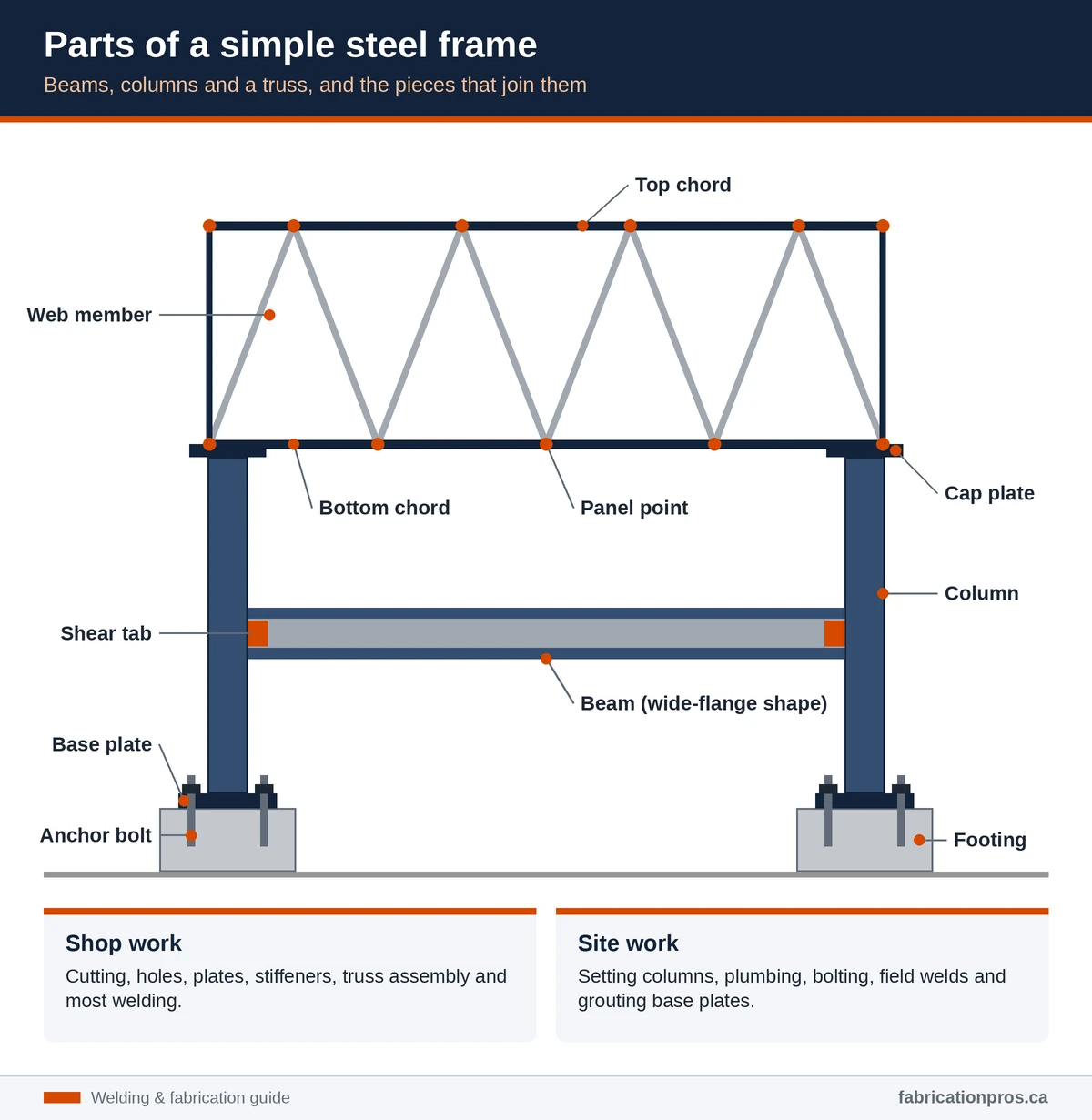
Every member, from a single lintel to a long roof truss, follows roughly the same path through the shop:
- Shop drawings are prepared and approved. Each piece gets a drawing with exact lengths, hole locations, plates and weld symbols. The engineer or designer reviews the drawings, and nothing should be cut until they come back approved.
- Material is ordered and tracked. Steel is bought to the specified size and grade. Mill test reports tie each heat of steel to its chemistry and strength, and the shop keeps that link so a piece can be traced if questions come up.
- Members are cut to length. Beams and tube are usually cut on a band saw. Plate parts are cut by plasma, oxy-fuel or shear depending on thickness and the shop’s equipment.
- Copes, notches and holes are made. A cope removes part of a beam flange so it can frame into another beam. Bolt holes are drilled or punched to the sizes on the drawing.
- Parts are fitted up. Plates, clips, stiffeners and base plates are located, squared and tacked in place. Measurements are taken from one reference point on the member so small errors do not add up along the length.
- The member is welded. Welds are made to the welding procedure for that joint, in a planned sequence that keeps heat and distortion under control.
- The piece is inspected. Welds are checked visually, dimensions are checked against the shop drawing, and any extra testing the specification calls for is completed.
- It is finished, marked and shipped. The member is cleaned and coated if specified, given its piece mark from the erection drawings and loaded so it can come off the truck in the order the erector needs it.
What changes for beams, columns and trusses
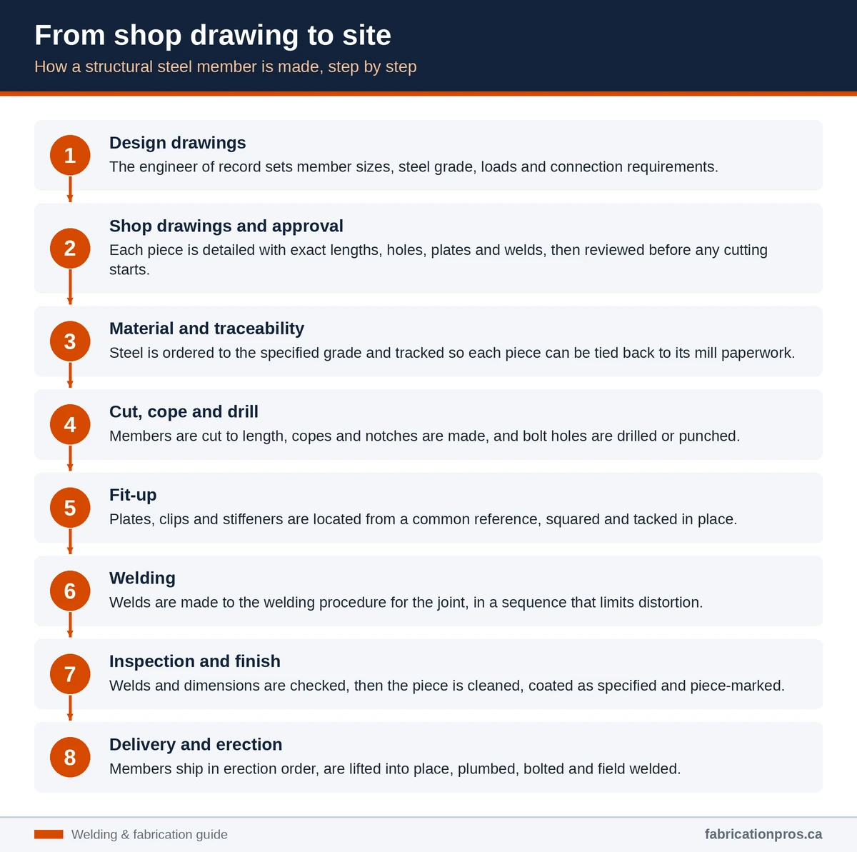
The process above is shared, but each type of member has its own details to watch.
Beams
A beam carries load across a span, so most of the shop work happens at the ends. End connections are usually shear tabs, clip angles or end plates, and they have to land exactly where the drawings say so the bolt holes line up with the supporting member. Where a beam frames into the web of another beam, the flange is coped so the two fit together. Stiffeners may be added where a heavy load or a column bears on the beam. Some beams are cambered, meaning given a slight upward curve so they settle closer to level once loaded. A cambered beam has to be marked so it goes up the right way.
Columns
A column carries load down to the foundation, so straightness and square ends matter most. The base plate is welded to the bottom of the column, and its bolt holes have to match the anchor bolts already cast into the concrete. Base plate holes are usually made larger than the bolts to allow for small placement errors, with plate washers on top. A cap plate or beam connection plates are added where beams or trusses sit on the column. The column length must allow for the grout space under the base plate, which is filled after the column is plumbed.
Trusses
A truss is a set of straight members, the top chord, bottom chord and web members, joined at panel points to form triangles. Trusses span longer distances using less steel than a solid beam, but they take more fitting and welding. Shops usually lay trusses out on a jig or layout table so every truss in the set comes out the same. Welding is balanced from side to side to limit bowing, and the finished truss is checked for overall length, depth, camber and straightness. Long trusses may be built in sections and spliced on site when they are too large to ship in one piece. Trusses are also flimsy sideways until they are braced, which affects how they are lifted.
Tolerances and why fit-up matters
Steel is never perfectly straight or perfectly sized. Rolled shapes arrive with mill tolerances on depth, flange squareness and straightness, and the fabrication standard named in the project specification adds limits for finished length, sweep, camber and hole location. The shop’s job is to stay inside those limits on every piece.
Good fit-up is where that happens. When plates are located from the same reference and joints are fitted with the gaps the welding procedure allows, weld sizes come out consistent and the member stays true. Poor fit-up causes oversized welds to fill gaps, more heat, more distortion and pieces that fight the erector on site. Welds also shrink as they cool, so experienced fitters plan for it in long members and trusses.
Tip: if new steel is connecting to an existing building, such as a renovation, a mezzanine or a beam replacing a wall, have the existing conditions field-measured before shop drawings are finished. Old buildings rarely match their original drawings.
Welding and inspection basics
Most shop welding on structural members uses wire-feed processes because they are fast and produce consistent welds. Flux-cored arc welding (FCAW) is widely used on structural steel, and gas metal arc welding (GMAW, or MIG) is common on lighter members. Stick welding (SMAW) is still a staple in the field because it handles wind and awkward positions well. Our guides to flux-cored arc welding and stick welding explain how each process works.
Two weld types do most of the work. Fillet welds are the triangular welds that join plates at a corner or tee, such as a shear tab to a column. Groove welds fill a prepared joint between two pieces and are used where the full strength of the member has to carry through, such as some splices and moment connections. Thicker steel may need preheat before welding, as set out in the welding procedure, to prevent cracking.
Inspection normally starts with a visual check of every weld for size, length, profile and surface defects, plus a dimensional check against the shop drawing. Where the specification calls for it, an inspector adds non-destructive testing such as ultrasonic or magnetic particle testing on selected welds. In Canada the welding standard for steel structures is commonly CSA W59, and the project specification will say which standards apply and who carries out the inspection, so read that section before the job is priced.
Delivery and setting steel on site
This is the part of the job most people see: members built in the shop to size, then delivered and set in place on site. A smooth day of erection depends on preparation done weeks earlier.
- Anchor bolts checked first: bolt locations and elevations should be surveyed before steel arrives. Bolts that are out of position are one of the most common reasons a column will not go down.
- Access and laydown: the crane needs firm ground and room to set up, and the truck needs a place to unload close to where the steel goes.
- Erection sequence: columns usually go first, then beams to tie them together, then trusses or joists. Temporary bracing or guying holds the frame until permanent bracing and decking are in.
- Plumb, bolt, then weld: columns are plumbed with shims or levelling nuts, connections are bolted, and field welds are made once the frame is aligned. Base plates are grouted last.
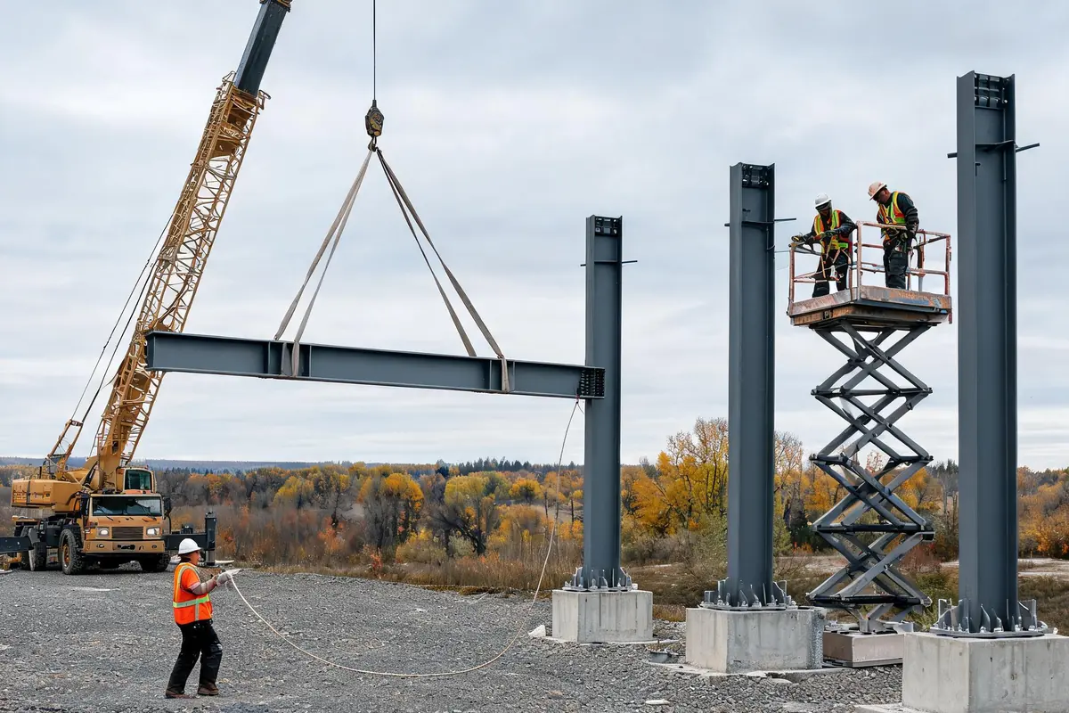
Field welding on Calgary job sites has its own challenges. Wind can blow away shielding gas and cold steel may need preheat, so welders often use screens or enclosures and choose processes suited to outdoor work. Our new construction welding page explains how shop and on-site welding fit into a build.
| Shop welding | Field welding |
|---|---|
| Controlled indoor conditions | Exposed to wind, cold and weather |
| Pieces can be turned so most welds are flat or horizontal | Welds are made where the joint sits, often vertical or overhead |
| Easier to fit, measure and inspect | Needs safe access, lifts and fall protection |
| Best for most connection plates and truss assembly | Used for final connections, splices and site changes |
Because shop welds are easier to control, good detailing keeps as much welding in the shop as possible and designs field connections to be bolted where the engineer allows it.
Common mistakes that slow a steel job
- Building from the wrong revision: drawings change during design. Make sure the fabricator has the latest approved set and that superseded sheets are clearly marked.
- Late changes: moving a beam or adding an opening after cutting starts usually means reworked or scrapped steel. Settle the layout before shop drawings are approved.
- Coating over field weld areas: paint or galvanizing where a field weld will go has to be removed on site. Mask those areas, or any bolted faying surfaces the specification requires to stay bare.
- Unclear scope: who supplies anchor bolts, who erects, who does the field welding, who provides the crane? Gaps in scope become extras later.
- Ignoring shipping size: very long or wide members need special trucks or permits. A splice location chosen early is easier than a surprise at the shipping stage.
- Mixed-up piece marks: similar-looking members in the wrong spot cause delays and fit problems. Clear marks and a clean erection drawing prevent this.
What to have ready before you ask for a quote
A fabricator can price a job accurately and quickly when the basics are in hand. Before you call, gather as much of this as you can:
- Structural drawings, stamped if available, plus any architectural sheets that show the steel.
- The steel section of the project specification, including coating, inspection and testing requirements.
- The scope you want quoted: fabrication only, or fabrication with delivery, setting and on-site welding.
- Finish: bare, primed, painted or galvanized.
- The site location and access, and whether new steel ties into an existing structure.
- Your schedule, including when the foundations and anchor bolts will be ready.
If you are still early in planning, our planning guide for hiring welding and fabrication services walks through the decisions to make first. When you are ready to talk about building beams, columns or trusses, see our structural beam, column and truss fabrication services page for what we build in the shop and on site.
Planning a structural steel job?
At Fabrication Pros, beams, columns and trusses are built in the shop to size, then delivered and set in place on site. If you have drawings ready or just a rough idea for a project in Calgary, Alberta, Canada, send them over and we will talk it through. You can also visit our structural fabrication page or contact us for a free quote.
Contact us with any questions you may have.